566
Проект смотритель. Часть 7. Железо
Эта статья является частью цикла
- Проект смотритель. Часть 1. Начало
- Проект смотритель. Часть 2. Дизайн
- Проект смотритель. Часть 3. Фоторезист
- Проект смотритель. Часть 4. Шасси
- Проект смотритель. Часть 5. Гусеницы
- Проект смотритель. Часть 6. Моделирование и печать
- Проект смотритель. Часть 7. Железо
- Проект смотритель. Часть 8. Софт
- Проект смотритель. Часть 9. Зарядная станция
- Проект смотритель. Часть 10. Bluetooth
- Проект смотритель. Часть 11. Home assistant
- Codex написал WASD управление для Смотрителя
Схему устройства я уже показал, давайте здесь чуть больше рассмотрим физические компоненты устройства.
Само устройство:
- Esp32cam - основной мозг - можно ещё найти под названием AI thinker.
- Широкоугольная камера с удлиненным шлейфом - угол обзора не так критичен, как длина шлейфа. В варианте с коротким шлейфом было бы сложнее придумать эстетически приятный корпус.
- Wifi антенна с коннектором - часто идёт в комплекте с платой.
- 3 li-ion батареи, соединенные последовательно (12.6v) с держателями.
- 2 dc-dc понижающих преобразователя (на 12v и на 5v).
- Драйвер двигателя 2-канальный - L298N, L293D или аналог - у меня L293D из-за меньших габаритов платы, хотя моделировал под L298N.
- 2 моторчика GA12-N20 с передаточным числом 150 (можно брать 200 - будет резвее).
- 12 подшипников 6803 (по два на колесо).
- BMS плата зарядки (если планируете заряжать в устройстве).
- Переключатель для подачи питания с батареи.
- Mosfet IRLML0030 + 1 кОм резистор для управления светодиодами.
- Светодиоды и резисторы - по вкусу.
Все остальные детали - из пластика, распечатаны на принтере (включая гусеницы).
Зарядная станция:
- Блок питания 12.6V 2A.
- Соответствующий разъём питания для корпуса.
- Вольтамперметр (желательно менее мощный до 5А, иначе небольшой ток не будет показывать).
- Контактная пара - у меня это медные пластины и стержни.
- Пара пружин для лучшего контакта при зарядке.
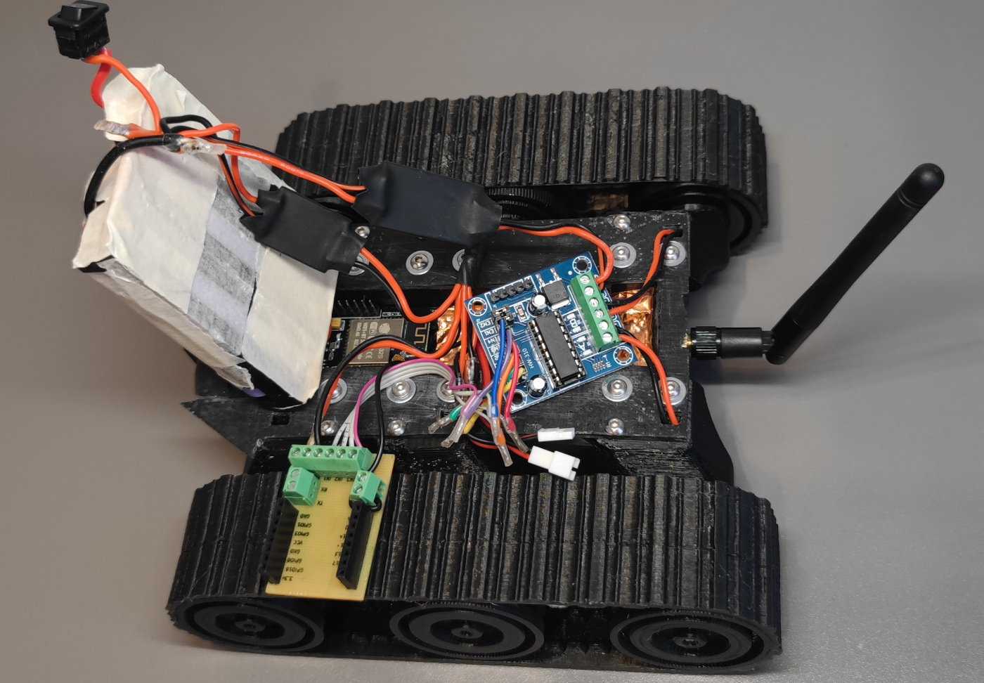
Компоновка всего этого железа в корпусе следующая:
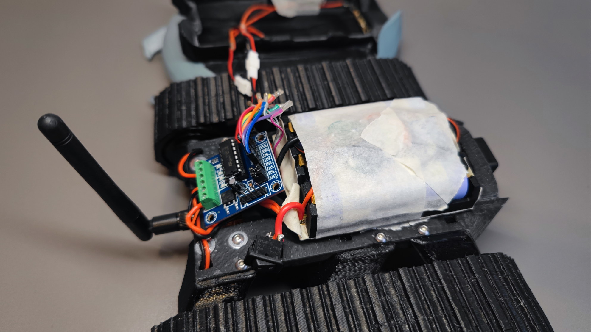
Если немного раскидать, чтобы были видны основные компоненты:
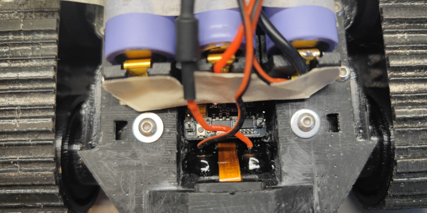
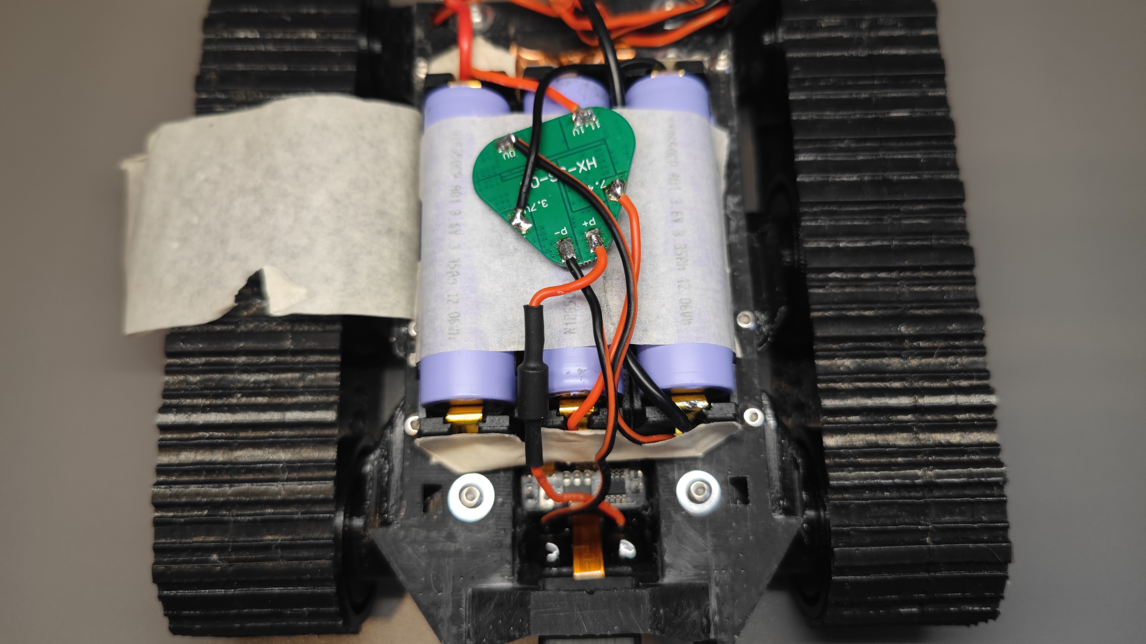
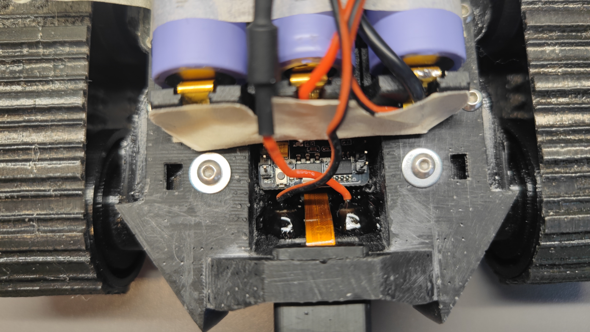
А здесь BMS плата зарядки, от которой провода идут на контактные стержни:
Вот эти стержни, залиты все той же смолой, из которой печатался корпус на фотополимерном принтере. Заливал послойно и засвечивал УФ-фонариком:
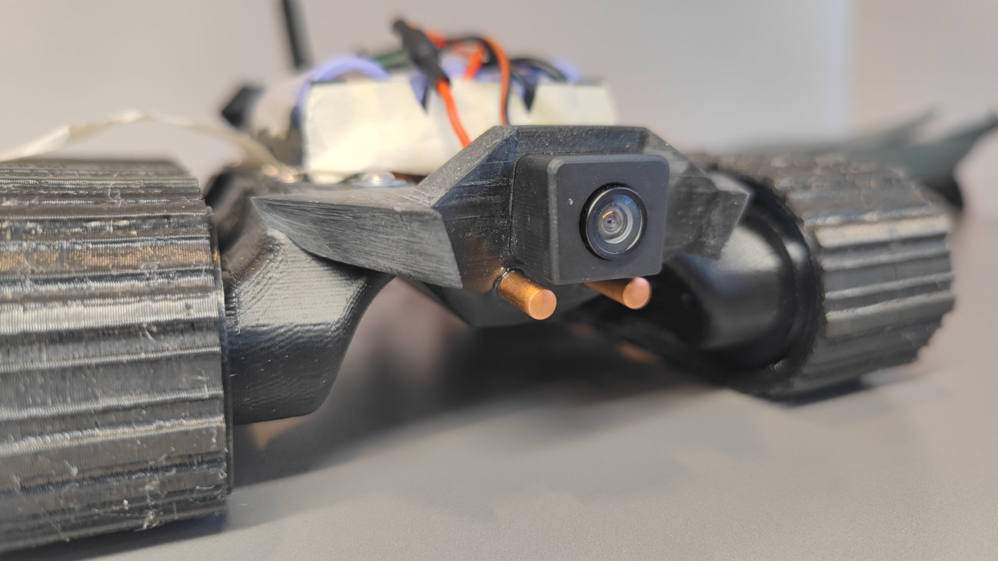
И вот так стержни выглядят спереди. Бокс камеры и сама камера внутри никак не зафиксированы, бокс держится на плотной посадке (и при редком падении, как показала практика, может выпасть), а камера за счет упругости шлейфа. Это еще дает забавный эффект - если надавливать на камеру - она прячется в корпус, но затем обратно вылазит. Буду считать это защитой от механических повреждений линзы.
И казалось бы все готово, но нет, впереди еще статей 5 о проекте.
Комментариев пока нет
-

Goback - простые бэкапы
Решил тут наконец заняться бэкапами. И без самописных утилит не обошлось. -

Проект Наблюдатель
Проект приурочен к хеллоуину - это статуя одноглазого ктулху с механизированным… -

Универсальный AI Telegram Bot
Хотите в пару действий запустить собственного AI бота для Telegram? -

Анализ истории просмотров Youtube
Задумывались, сколько времени вы проводите за просмотром видео? Давайте считать. -

Image2model с tripo3d и Blender
Иногда хочется, чтобы нарисованный или сгенерированный персонаж стал настоящим -

Локальный эмулятор Telegram
Писали ли вы когда-нибудь телеграм ботов?