38
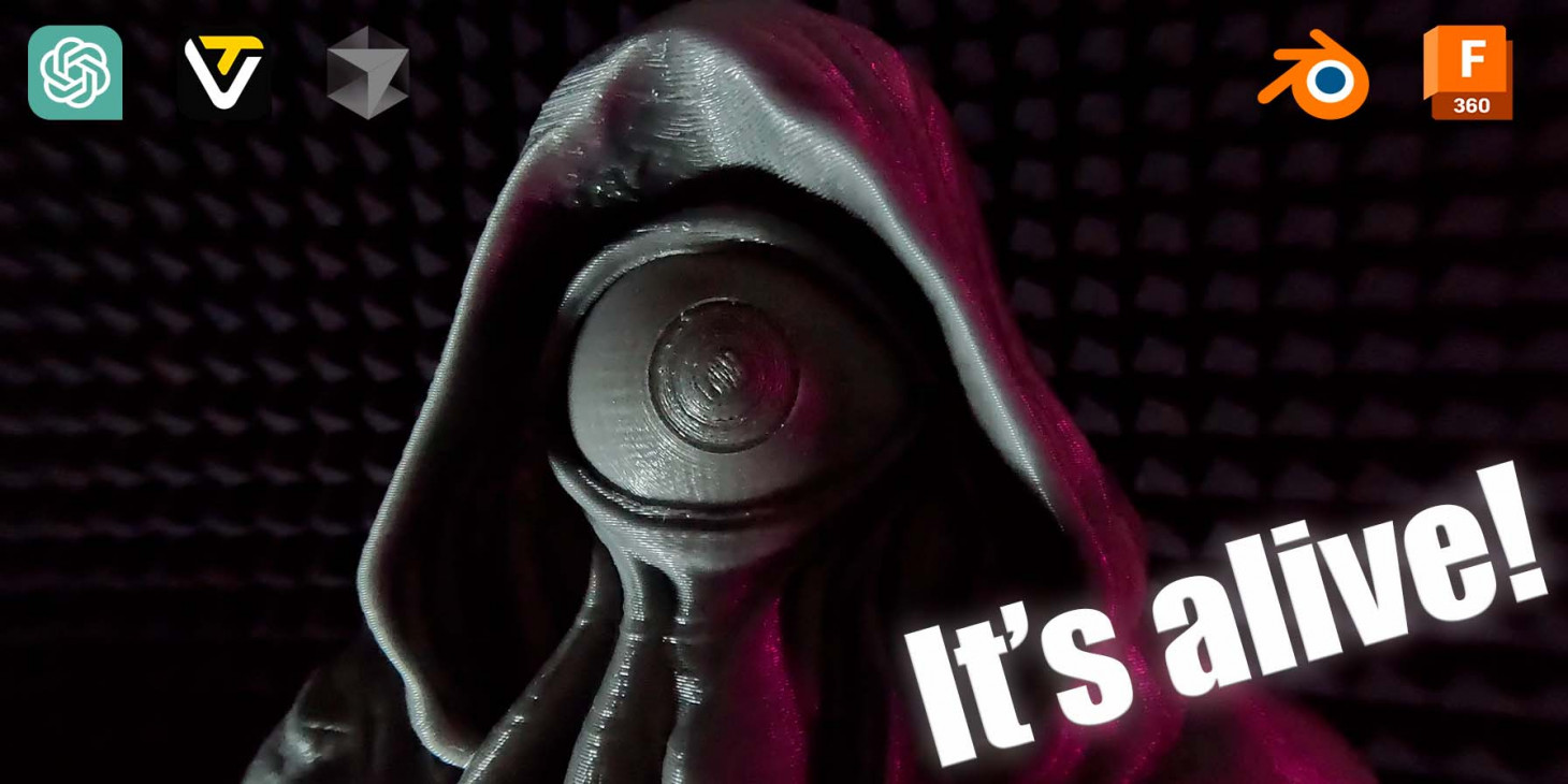
Проект Наблюдатель
Началось все с того, что я задался целью сделать что-то интересное и несложное к хеллоуину, так что сам бог велел сделать что-то этакое. Это должен был быть проект выходного дня.

Основная идея появилась быстро - буквально первым пришло на ум сделать механизированный глаз. Причем чтобы он обязательно вращался в 2 направлениях - нужно же бросить вызов своему инженерному гению. В сети вариантов исполнения, которые бы я хотел повторить, не нашлось - так что расчехлил Fusion 360 и пошел проектировать.
Изобретать колесо я уже умею, на прошлом проекте встроил внутрь гусеничного шасси моторчики. Здесь поступить решил также - никаких шарниров или поводков - только прямой привод, только хардкор. Для реализации 2-осевого управления нам нужно разместить 2 сервы перпендикулярно друг другу, чтобы одна из них вращалась на второй. Первый прототип вышел достаточно громоздким даже при использовании мелких сервоприводов. Но дома валялись 2 самых распространенных сервопривода SG-90, так что решил собрать прототип на них.
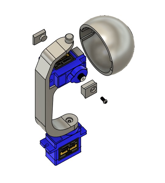
Оптимизировал размеры как мог, еще меньше при прямом приводе сделать габариты на этих сервах не выйдет - по внешнему диаметру глаз получился размером в 42мм. Долго ломал голову, как закрепить серву внутри так, чтобы она и легко вставлялась, и не портился внешний вид сферы (т.е. никаких шурупов, закручивающихся снаружи). Ответ пришел из столярки - ласточкины хвосты. Замоделировал крепление сервы и 2 проставки - одну для передачи управления с сервы, вторая является осью вращения.
Проще понять как это работает на практике - прикручиваем серву, затем присоединяем коннекторы и вставляем в глаз. Таким образом можно легко перепечатывать отдельные элементы, например, заменять глаз.
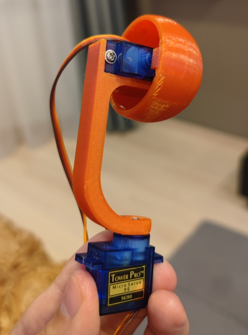
Печатаем детали, примеряем - все подходит.
Софт
Что насчет управления?
Раз уж у нас век почти бесплатной разработческий силы в лице ИИ - решил собрать оригинальный интерфейс управления, Чтобы с драг н дропом, пресетами анимации и режимом хаоса (у нас же проект на хеллоуин, нужно больше безумия). Интерфейс собрал ChatGPT на своем canvas - не с первой попытки, но удачно.
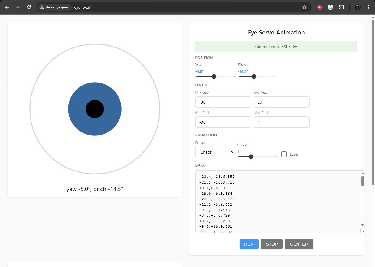
Дальше нужно прикрутить это все к железу - достаем из коробки Esp8266 в виде платы Wemos D1 mini и дописываем "бэкенд" под неё уже в Cursor. За основу берем уже написанный интерфейс, добавляем только API на бэкенд - управление по координатам, запуск анимаций и вот это все.
Подключаем, прошиваем, тестим... и получаем дерганную глючную фигню, которая стартует, но перезагружается при движении даже при питании от павербанка. Виноват ИИ? Нет, схемотехника. Сервы, даже эти мелкие SG-90 потребляют в пике больше 1 ампера каждая (если движения не сглаживать - а я хочу что-то безумное и дерганное). Чисто для тестов запитал контроллер напрямую от usb порта ноутбука, а сервы оставил питаться от павербанка. Главное соединить землю при таком питании.
Запускаем - все крутится и слушается как должно. Чтобы исправить питание добавить в схему конденсатор вместо второго питания. Пока переключимся на что-то более интересное.
Модель
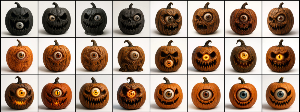
Начинка есть, что по внешности? Вновь зовем на помощь ИИ. Что одноглазое можно сделать на хеллоуин? Конечно, какого-нибудь монстра. Не тыкву же. Ну просто посмотрите, какую тыкву?
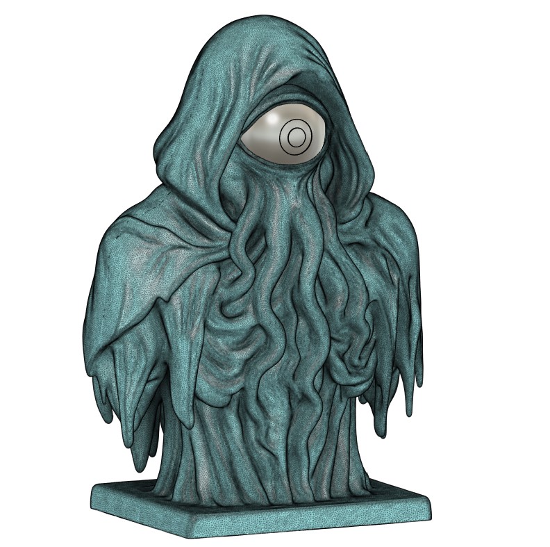
Какое-то время перебирал варианты, пока не получил эту статую.
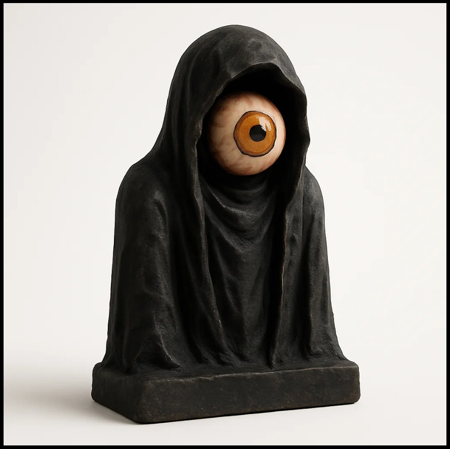
Выглядит уныленько, но в концепт вписывается. Давайте посмотрим до чего можно эту идею развить. Фентези? Уже лучше. Фентези хоррор? Сплошь какие-то зомбаки и полускелеты получаются.
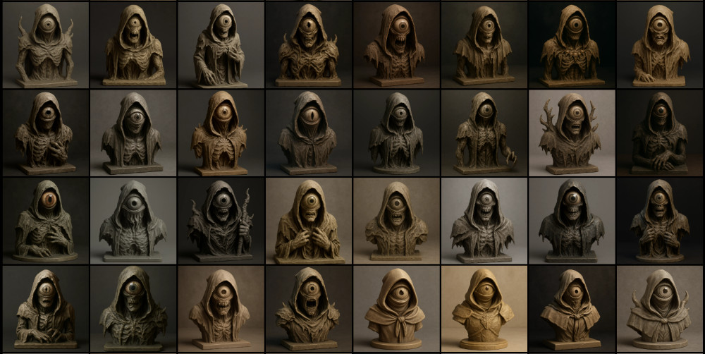
Киберхоррор - уже интереснее и в тему, но сложновато в реализации как по отрисовке модели, печати и встраивании начинки.
Тем не менее это был мой основной вариант, пока я не увидел это...

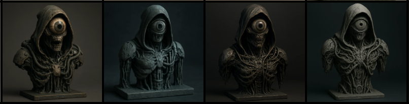
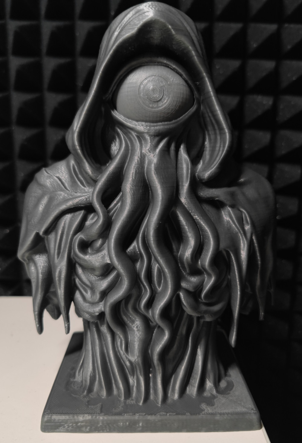
Сошедшее со страниц Лавкрафта чудовище, внушающее ужас одним своим видом - идеальное попадание по все сразу.
Берем картинку, запускаем генерацию модели в tripo3d и на выходе получаем 3д-модель. Скачиваем STL и открываем в blender - местами выглядит кривовато, поэтому допиливаем руками в режиме скульптинга. Основное, конечно - натянуть глаз на ... сферу.
Далее нужно придумать каким же образом нашу начинку размещать внутри, и не просто размещать, а как вообще её туда засовывать.
Очевидно, единственный путь - снизу. Раньше я бы импортировал mesh во Fusion 360, конвертировал в твердое тело и вырезал по месту все, что нужно. Но такой метод показал полную несостоятельность на прошлом проекте. Работат с таким мешем дается Fusion тяжело из-за большого количества треугольников. Поэтому я пошел от обратного и замоделировал кожух, который впоследствии нужно будет в blender вырезать из stl.
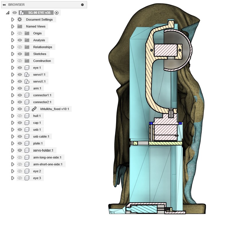
Выглядит он на первый взгляд монструозно, давайте проведу краткий экскурс по техническим решениям:
- сам механизм будет вставляться снизу и затем защелкиваться движением вперед. Для этого я добавил на крепление оси Х отдельный кронштейн с выступом, который будет фиксироваться в оболочке. Причем он тоже хитрый - чтобы иметь возможность отогнуться вниз - глаз должен быть повернут вниз. Почему нельзя было обойтись односторонним креплением к серве? Потому что так глаз можно было бы вдавить внутрь фигуры из-за длинного рычага. Для проверки работы отрезал нужную часть модели прямо в слайсере, распечатал и подтвердил работоспособность - все гуд.
-
в кронштейне также добавлено отверстие по центру, чтобы была хотя бы теоретическая возможность вставить в него отвертку и таким образом закрутить шуруп в серву. При этом нужно будет отогнуть верхнее крепление, да и найти длинную подходящую отвертку;
-
попутно дозаказал еще 2 сервы, ну так, на всякий случай. И оказалось что рандомные китайские сервы действительно рандомные - они буквально с разными габаритами, хотя обе заявлены как SG-90. Из критичного - докупленные оказались на 1мм выше, так что пришлось дорабатывать модели, чтобы они имели возможность стыковки с обоими вариантами.
-
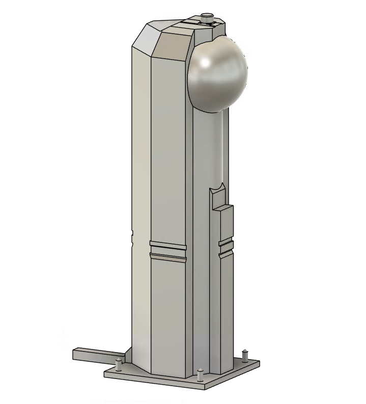
допустим, сам механизм у нас размещен - Как его закрепить? Изначально планировал закрепить серву оси Х болтом снизу как-то так (схема), но решил, что такую длинную и узкую отвертку все же будет проблематично найти. И в лучших традициях оверинженеринга я спроектировал упоротого робота. Не специально, правда. Давайте покажу как так вышло. Серва должна на что-то опираться, разумно, что нужна какая-то пластина. До дна от сервы далековато, чтобы крепить её аж оттуда. Остаются только стенки. Причем стенки уже и так с одной стороны минимальных размеров - уменьшать некуда. С другой стороны - расширять тоже некуда, по нижней части модели вырез впритык подходит к модели. Т.е. полноценные уши для прикручивания будут только мешать. Собственно, ничего умнее каких-то защелок я не придумал. На стенках разместил выступы шириной в 1мм, чтобы не мешать вставке механизма, и также сделал пластину с отгибаемыми "ушами" первым попавшим в голову способом. Для проверки я распечатал кусок модели и пластину - на удивление все заработало. При должной сноровке даже выщелкивается обратно.

- ну и остальное уже не так интересно - питание будет по usb-C, так что нужно замоделить какое-то крепление. Тащить разъем наружу я не захотел, тем более что в центре есть достаточно места - так что быстро отрисовал модель разъема и кабеля и вокруг них собрал корпус. Не забыл и про выступы в пазе, чтобы провод никуда не выпадал и достаточно надежно держался в своей нише.
Печать
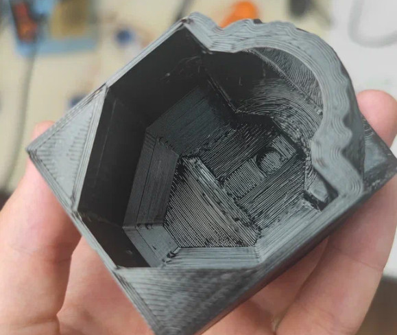
Если вы достаточно наблюдательны - могли заметить что углубление для крепления кронштейна внутри фигуры тоже хитрое - сделано в несколько слоев, чтобы при печати не требовались поддержки и все напечаталось мостами. Лайфхак знаю давно, но применяю редко - не всегда нужно отверстие размещать где-то высоко.
Большие фигуры я печатаю не так часто, тем более некоторые элементы здесь достаточно ... своеобразны. Провел несколько тестов наиболее интересных мне частей модели:
-
голова - было интересно как распечатается сфера глазницы, а также полость для вставки, все подошло
-
часть заднего плаща со свисающими элементами - все знают, какая боль печатать нечто такое в воздухе на поддержках, но на удивление все прошло гладки. Выступы буквально выросли не держась почти ни за что. Ну и здесь же бонусом проверил вставляется ли кабель в паз и как там держится - меня устроило, корректив не вносил.
-
несколько вариантов креплений, коннекторов и глаз. По большей части из-за новых серв с большими габаритами.
Ну и теперь сама модель - несмотря на успешные тестовые попытки - здесь не все прошло гладко и часть висюлек все же отвалилось. Еще часть удалось спасти вовремя руками и 3д-ручкой, буквально приклеил ей к столу заново оторванную поддержку.
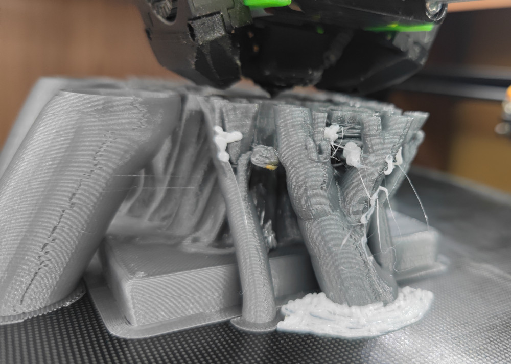
В остальном - никаких проблем. Аккуратно отрываем поддержки, убираем лишнее и у нас все готово к сборке.
Ну и собираем:
Процесс сборки и демонстрацию лучше смотрите на видео - это полноценный DIY ролик от начала и до конца, в котором куда больше контента.
P.S. заметил, что после перехода на видеоконтент я почти перестал делать фото процесса, вместо этого есть куча видео. Поэтому в рамках этой статьи картинок не так много, да и то часть пришлось вырезать из видео. Нужно как-то держать в голове, что нужны и фото и видео.
Видео на русском: https://www.youtube.com/watch?v=e7KyU8zBTnY
Комментариев пока нет
-

Продолжаем печать после отключения
Печать идет больше суток и в процессе пропадает свет. Знакомо? -

Как я работу в 2026 году менял + бонус
После 10 лет в e-commerce я вышел на рынок -

Goback - простые бэкапы
Решил тут наконец заняться бэкапами. И без самописных утилит не обошлось. -

Универсальный AI Telegram Bot
Хотите в пару действий запустить собственного AI бота для Telegram? -

Анализ истории просмотров Youtube
Задумывались, сколько времени вы проводите за просмотром видео? Давайте считать. -

Image2model с tripo3d и Blender
Иногда хочется, чтобы нарисованный или сгенерированный персонаж стал настоящим